8.3 The Emboss and Bump map Filters
There are two filters that are particularly useful for rendering.
These are Emboss and Bump map.
The Emboss filter, found in Image:Filters/Distorts,
creates the effect that an image is embossed into a thin metal plate.
Figure
8.9
Figure 8.9:
The Emboss Filter Dialog
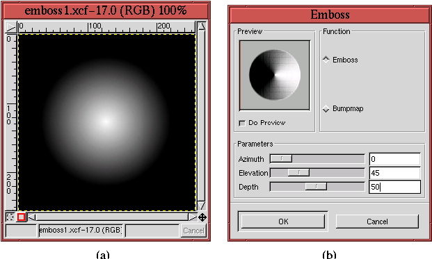 |
illustrates the use of the filter for a very simple case.
Figure
8.9(a) shows an image that was created
using a radial gradient, and Figure
8.9(b) shows
the corresponding dialog for the
Emboss filter. The dialog
consists of a preview, two radio buttons labeled Emboss and Bumpmap,
and three sliders called Azimuth, Elevation, and Depth.
The three sliders in the filter dialog control the embossing effect,
and Figure
8.10
Figure 8.10:
Geometric View of the Emboss Filter Options
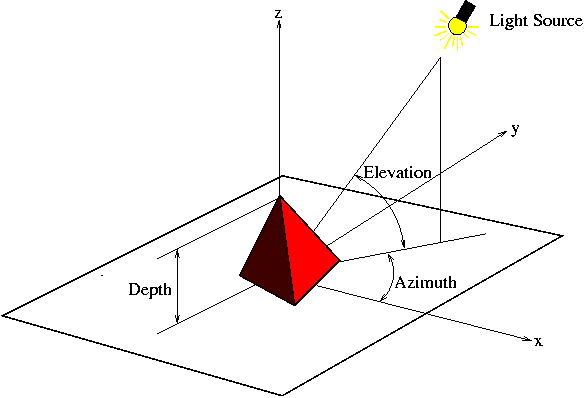 |
shows a 3D scene that defines the effect of each one. In the scene
there is a pyramid object illuminated by a light
source. Two angles, the Azimuth and Elevation,
define the position of the light with respect to the pyramid. The
Azimuth describes the light source's angular position in the
horizontal plane, similar to a compass bearing. The Elevation is the
angular measure of the source above the plane.
When the light source is on one side of the object, the other side
must be in shadow, as shown in Figure
8.10. When
the Elevation is 90o, the light source is positioned vertically
over the object, and all faces are equally well illuminated, which
eliminates the shadow. There is, however, more reflected light coming
from surfaces that are perpendicular to the rays of light than from
those that are oblique. Thus, Azimuth and Elevation control the
direction of light and shadow.
``Wait a minute! That's fine for a 3D object,'' you might say. ``But
we are working with flat images...how does Emboss determine
the relative angles for something that, in reality, is completely
flat?'' I was hoping you would ask. Figure
8.11
Figure 8.11:
How Emboss is Applied to a 2D Image: Magnitudes of the Gradient Vectors
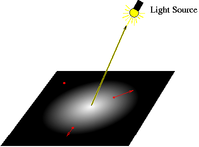 |
shows the radial gradient from Figure
8.9(a) in
a 3D context. That is, the image is 2D, but an imaginary light source
is positioned over it at some azimuth and elevation. The little red
arrows shown in the image plane explain how the filter embosses the
image.
The red arrows, called gradient vectors, are
computed for each pixel in the image (only three are shown in
Figure
8.11). For each pixel, the gradient is
drawn in the direction that pixel values decrease the fastest, and the
length of the arrow is determined by the amplitude of that change.
Thus, in Figure
8.11, there are two arrows each
pointing from their pixels in the direction of greatest change, and
one is longer than the other because its slope of change is greater.
The third arrow is just a dot because it is located in a region where
there is no change in pixel value. Its length is zero.
The Emboss filter works by computing the amount each pixel's
gradient vector projects along the vector from the pixel to the light
source. You can see that the gradient vector labeled a in
Figure
8.12
Figure 8.12:
How Emboss is Applied to a 2D Image: Directions of the Gradient Vectors
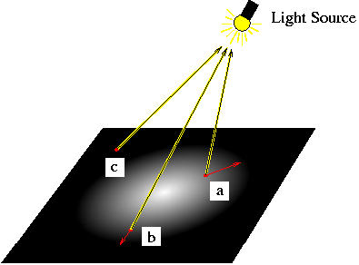 |
has a positive projection onto the vector pointing towards the light
source. Alternatively, the gradient vector labeled
b has a negative
projection because it points away from the light source. Finally, the
gradient vector labeled
c has no component along the direction to the
light source. Its projection is zero.
Gradient arrows that have a large positive projection in the light
source direction are mapped to lighter grays up to the maximum
projection, which is mapped to white. Gradient arrows that have
negative projections are mapped to darker grays up to the maximum
negative projection, which is mapped to black. Pixels whose gradient
arrows have no component in the light source direction are mapped to
the midtone gray,
127R 127G 127B. Exactly how much light or dark
is used in the map depends on the third slider control, labeled Depth
in the Emboss dialog (see Figures
8.9(b)
and
8.10). A Depth value of zero produces no
shadow, and a large value produces a deep, well-defined one.
Referring back to Figure
8.9(a), the Azimuth
slider is set to zero. This means that the light source is positioned
to the right of the image. Furthermore, the Elevation slider is set
to 45o, meaning that the left side of the image is in the shadow
zone. This agrees with the vector analysis given earlier. The pixels
on the left side of Figure
8.9(a) have gradient
vectors that point away from the light source, and so these pixels are
mapped to darker values. The pixel values on the right side have
gradient vectors pointing towards the light source, so their pixels
are mapped to lighter values. The result is the embossed image looks
like a cone, which can be seen in the image preview area in
Figure
8.9(b).
So much for the theory. How about an example?
Figure
8.13(a)
Figure 8.13:
Example of Using the Emboss Filter
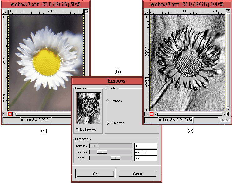 |
illustrates the photo of a daisy, and
Figure
8.13(c) shows the result of applying the
Emboss filter to it. The filter options are shown in
Figure
8.13(b). The result is impressive.
Figure
8.13(c) shows a version of the daisy that
appears to be embossed into a thin sheet of metal.
You should note that, although the result of the Emboss filter
is a grayscale, it is still an RGB image. Furthermore, it is
important to know that Emboss does not work on images with an
alpha channel. The alpha channel must be removed by choosing Flatten Image from the Layers menu before the
image can be embossed. Flatten Image is described in more
detail in Section
2.7.2.
A filter that works in a manner similar to Emboss is Bump
map, which is located in the Image:Filters/Map menu. The Bump map filter is more versatile
than Emboss, and it is very useful for rendering (see
Sections
8.6 and
8.7 for two interesting applications of bumpmapping).
The Bump map filter works by embossing one image and then
multiplying the result with another image. This creates the effect of
embedding the texture of the first image into the second. The
filter's dialog has many options that control the final effect.
Figures
8.14
Figure 8.14:
Cape Cod from Space and a Pattern Texture
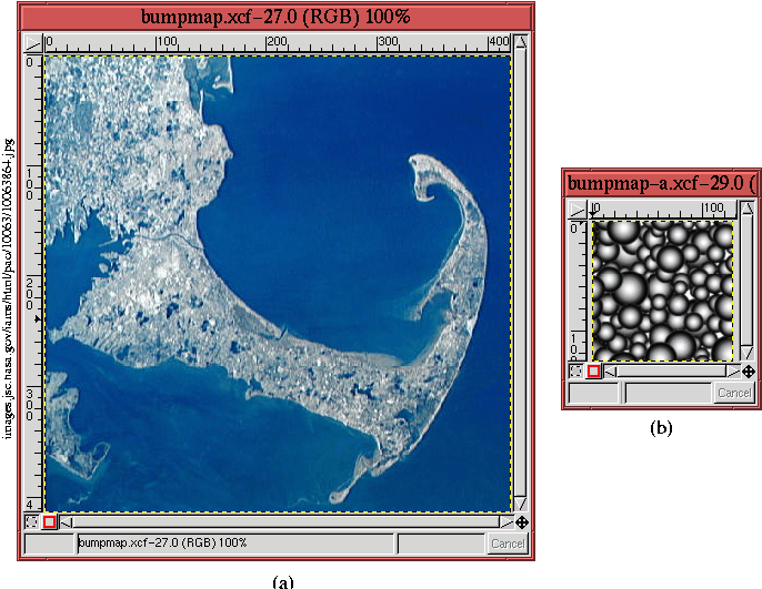 |
and
8.15
Figure 8.15:
Applying the Bump map Filter to Cape Cod
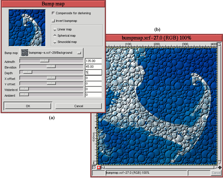 |
illustrate an example of using
Bump map.
Figure
8.14(a) shows a photo from space of Cape
Cod in the great state of Massachusetts, and
Figure
8.14(b) shows a small image created by
filling with a pattern selected from the
Pattern Selection
dialog. These two images are the raw materials used by
Bump map
in what follows.
Figure
8.15(a) shows the Bump map dialog,
and Figure
8.15(b) shows the result of applying
the filter to Figure
8.14(a) using the image in
Figure
8.14(b) as the embossing map. As you
can see in Figure
8.15(a), the Bump map
filter dialog has a few more options than the Emboss filter.
The most important is the menu labeled Bump map (not to be confused
with the filter name). Clicking on this menu provides a list of all
the layers in all open images, and the image layer chosen in this menu
is the one that is used as the embossing map. However, unlike the
restriction of the Emboss filter, Bump map allows any
layer, with or without an alpha channel, to be used. The Bump
map dialog also has all the usual options for embossing: Azimuth,
Elevation, and Depth.
Bump map also has a number of additional options. There are X
Offset and Y Offset, which are useful for positioning the embossing
image with respect to the embossed one. There is also the Waterlevel
option which is only useful if the embossing image has an alpha
channel. In this case, the embossing is applied as a function of the
alpha and Waterlevel values. Low values of alpha diminish the
embossing effect, and high values increase it. This is modulated by
the value of Waterlevel. High values of Waterlevel accentuate the
alpha channel effect, and low values proportionally diminish it.
The Ambient option in
the Bump map dialog controls the relative strength of the
directional light source (refer back to
Figure
8.10). An ambient
light source is one that shines equally from all directions. This is
the kind of illumination that is useful in a photography studio, where
all shadows on a subject must be eliminated. A strong ambient light
source cancels the effect of a directional one. A directional light
source creates shadows because it illuminates a scene from a single
direction, but the more ambient light there is, the weaker the shadow
making effect of the directional light becomes. Thus, you can use the
Ambient option in the Bump map dialog to control the relative
amount of directional light and, in so doing, control the strength of
the shadows.
Multiplying an embossing map with an image produces a result that is
darker than either of the first two. This is a natural result of
image multiplication (see the description of the Multiply
blending mode in Section
5.6). The Compensate for
Darkening checkbox reduces this effect. The Invert Bumpmap checkbox
simply inverts the relationship of shadow and light in the embossing
map.
Finally, there are three radio buttons that control the multiplication
process. These are labeled Linear Map, Spherical Map, and Sinusoidal
Map. The Linear Map option does a straight multiply of the embossing
map with the image. The Sinusoidal and Spherical Map options,
however, act somewhat like the Curves tool (see
Section
6.2.1). That is, the effect of the embossing map is
warped according to a curve. The sinusoidal curve provides more
contrast to the midtone embossing values and the spherical curve more
to the shadow and highlight values. This may sound a little
complicated, but it isn't. Just play around with them, and you'll see
right away what they do.
©2000 Gimp-Savvy.com
