6.4.4 Unsharp Mask Pitfalls
Applying Unsharp Mask can have its problems. For example, this
method of sharpening an image can sometimes introduce undesirable
color shifts.
Figure
6.35
Figure 6.35:
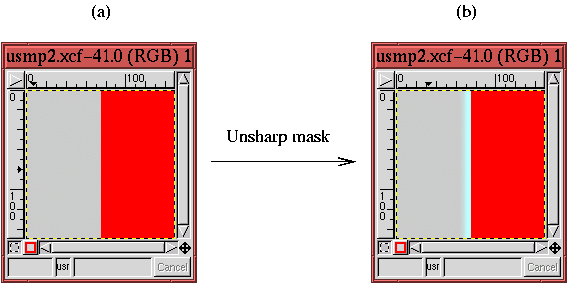
Example of Unsharp Mask Provoking a Color Shift
 |
illustrates just such a case. Figure
6.35(a) shows
an image with a single edge and with a gray region to the left of the
edge and a red region to the right. Figure
6.35(b)
shows the result of applying the
Unsharp Mask to this image.
You can clearly see a cyan colored halo just to the left of the edge
even though there is no apparent cyan in the original.
The explanation for this is as follows. Remember that each image is
composed of three color channels. Thus, the Unsharp Mask is
actually applied to each of the three channels individually and the
results are then combined. Imagine, then, that the color on the left
side of an edge consists of a low value of red and green but a high
value of blue. Furthermore, suppose that the region on the right side
of the edge has a high value of red and green but a low value of blue.
This situation presents you with an edge that goes from dark to light
in the Red and Green channels but from light to dark in the Blue.
According to the preceding description, the Unsharp Mask makes a
dip for the Red and Green channels on the left side of the edge but a
peak for the Blue. Clearly, when adding the Red, Green, and Blue
channels, the two dips plus the one peak do not create a color whose
relative mix has been maintained. In plain language, this means the
hue has been changed.
This is just what has happened in Figure
6.35. The
color region to the left side of the edge is a medium gray. Thus, it
consists of medium values of red, green, and blue. The right side of
the edge is composed uniquely of a high value of red and low (zero)
values of green and blue. Thus, the application of the Unsharp
Mask creates peaks in the Green and Blue channels of the gray region
but a dip in the Red. This explains where the cyan halo comes from,
removing red from an image makes it look more cyan.
In most images, the creation of an off-color halo does not occur or is
not evident. But when it does happen, don't worry; there is a
technique to correct the problem. Figure
6.36
Figure 6.36:
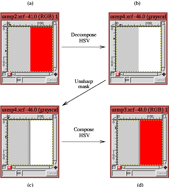
Circumventing the Unsharp Mask Color Shift Problem by
Sharpening only the Value Channel
 |
illustrates the procedure. Figure
6.36(a) is
identical to Figure
6.35(a). The procedure first
decomposes the image into its hue, saturation, and value components.
This is done with the HSV option of the
Decompose function
(found in the
Image:Image/Channels menu). The value component
of the result is shown in Figure
6.36(b). The
Unsharp Mask is then applied uniquely to this value component, the
result being shown in Figure
6.36(c). Finally, the
hue, saturation, and sharpened value components are recomposed using
the HSV option of the
Compose function (also found in the
Image:Image/Channels menu). Figure
6.36(d) shows
the result of the processing sequence. As you can see, the edge has
been sharpened without creating a shift in hue at the edge.
Because the value component of the image only contains light and dark
information about the image, the sharpening is performed just where it
should be and no color shift occurs. Why isn't an HSV decomposition
built into the Unsharp Mask? Apparently, a few mysteries of the
unsharp persist...
The other important problem that the Unsharp Mask can create is
the amplification of noise. Noise is
sharpened just as are the other elements of the image, and if the
sharpened noise becomes too apparent, it can become a significant
detraction. An approach that can be used to avoid the problem is to
set a non-zero value of Threshold in the Unsharp Mask dialog.
Setting the threshold diminishes the effect of noise by applying the
mask only to edges that have jumps greater than the Threshold value.
©2000 Gimp-Savvy.com


