Administering Virtual Local Area Networks
A virtual local area network (VLAN) is a subdivision of a local area network at the data
link layer of the TCP/IP protocol stack. You can create VLANs for local
area networks that use switch technology. By dividing groups of users into VLANs,
you can improve network administration and security for the entire local network. You
can also assign interfaces on the same system to different VLANs.
Consider dividing your local network into VLANs if you need to do
the following:
Create a logical division of workgroups.
For example, suppose all hosts on a floor of a building are connected on one switched-based local network. You could create a separate VLAN for each workgroup on the floor.
Enforce differing security policies for the workgroups.
For example, the security needs of a Finance department and an Information Technologies department are quite different. If systems for both departments share the same local network, you could create a separate VLAN for each department. Then, you could enforce the appropriate security policy on a per-VLAN basis.
Split workgroups into manageable broadcast domains.
The use of VLANs reduces the size of broadcast domains and improves network efficiency.
Overview of VLAN Topology
Switched LAN technology enables you to organize the systems on a local network
into VLANs. Before you can divide a local network into VLANs, you must
obtain switches that support VLAN technology. You can configure all ports on a
switch to serve a single VLAN or multiple VLANs, depending on the
VLAN topology design. Each switch manufacturer has different procedures for configuring the ports of
a switch.
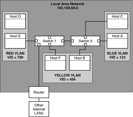
Figure 6-1 shows a local area network that has the subnet address 192.168.84.0. This LAN
is subdivided into three VLANs, Red, Yellow, and blue.
Figure 6-1 Local Area Network With Three VLANs

Connectivity on LAN 192.168.84.0 is handled by Switches 1 and 2. Systems of
the Information Technologies workgroup are assigned to the Blue VLAN. The Human Resources
workgroup's systems are on the Yellow VLAN. The Red VLAN contains systems in
the Accounting workgroup.
VLAN Tags and Physical Points of Attachment
Each VLAN in a local area network is identified by a VLAN
tag, or VLAN ID (VID). The VID is assigned during VLAN configuration. The VID is
a 12-bit identifier between 1 and 4094 that provides a unique identity for
each VLAN. In Figure 6-1, the Blue VLAN has the VID 123, the Yellow
VLAN has the VID 456, and the Red VLAN has the VID 789.
When you configure switches to support VLANs, you need to assign a
VID to each port. The VID on the port must be the same
as the VID assigned to the interface that connects to the port, as
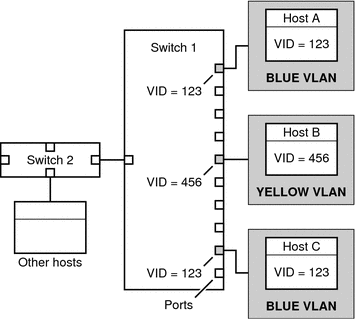
shown in the following figure.
Figure 6-2 Switch Configuration for a Network with VLANs

In this figure, the primary network interfaces of three hosts connect into Switch
1. Host A is a member of the Blue VLAN. Therefore, Host
A's interface is configured with the VID 123. This interface connects to Port
1 on Switch 1, which is then configured with the VID 123. Host
B is a member of the Yellow VLAN, with the VID 456. Host
B's interface connects to Port 5 on Switch 1, which is configured with
the VID 456, and so on.
During VLAN configuration, you have to specify the physical point of attachment, or PPA, of
the VLAN. You obtain the PPA value by using this formula:
driver-name + VID * 1000 + device-instance
Note that the device-instance number must be less than 1000.
For example, you would create the following PPA for a ce1 interface to
be configured as part of VLAN 456:
ce + 456 * 1000 + 1= ce456001
Planning for VLANs on a Network
Use the next procedure for planning for VLANs on your network.
How to Plan for VLAN Configuration
- Examine the local network topology and determine where subdivision into VLANs is appropriate.
For a basic example of such a topology, refer to Figure 6-1.
- Create a numbering scheme for the VIDs and assign a VID to
each VLAN.
Note - A VLAN numbering scheme might already exist on the network. If so, you
must create VIDs within the existing VLAN numbering framework.
- On each system, determine which interfaces should be members of a particular VLAN.
- Find out which interfaces are configured on a host.
# dladm show-link
- Identify which VID should be associated with each data link on the system.
- Create PPAs for each interface to be configured with a VLAN.
All interfaces on a system do not necessarily have to be configured on
the same VLAN.
- Check the connections of the interfaces to the network's switches.
Note the VID of each interface and the switch port where each
interface is connected.
- Configure each port of the switch with the same VID as the
interface to which it is connected.
Refer to the switch manufacturer's documentation for configuration instructions.
Configuring VLANs
The Solaris OS now supports VLANs on the following interface types:
Of the legacy interface types, only the ce interface can become a member
of a VLAN. You can configure interfaces of different types in the same
VLAN. For information about the interface types that are supported by the Solaris
OS, refer to Solaris OS Interface Types.
How to Configure a VLAN
- Assume the Primary Administrator role, or become superuser.
The Primary Administrator role includes the Primary Administrator profile. To create the role
and assign the role to a user, see Chapter 2, Working With the Solaris Management Console (Tasks), in System Administration Guide: Basic Administration.
- Determine the types of interfaces in use on your system.
# dladm show-link
The output shows the available interface types:
ce0             type: legacy    mtu: 1500       device: ce0
ce1             type: legacy    mtu: 1500       device: ce1
bge0            type: non-vlan  mtu: 1500       device: bge0
bge1            type: non-vlan  mtu: 1500       device: bge1
bge2            type: non-vlan  mtu: 1500       device: bge2
- Configure an interface as part of a VLAN.
# ifconfig interface-PPA plumb IP-address up
For example, you would use the following command to configure the interface
ce1 with a new IP address 10.0.0.2 into a VLAN with the VID
123:
# ifconfig ce123001 plumb 10.0.0.2 up
- (Optional) To make the VLAN settings persist across reboots, create a hostname.interface-PPA file
for each interface that is configured as part of a VLAN.
# cat hostname.interface-PPA
IPv4-address
- On the switch, set VLAN tagging and VLAN ports to correspond with the
VLANs that you have set up on the system.
Example 6-3 Configuring a VLAN
This example shows how to configure devices bge1 and bge2 into a
VLAN with the VID 123.
# dladm show-link
ce0             type: legacy    mtu: 1500       device: ce0
ce1             type: legacy    mtu: 1500       device: ce1
bge0            type: non-vlan  mtu: 1500       device: bge0
bge1            type: non-vlan  mtu: 1500       device: bge1
bge2            type: non-vlan  mtu: 1500       device: bge2
# ifconfig bge123001 plumb 10.0.0.1 up
# ifconfig bge123002 plumb 10.0.0.2 up
# cat hostname.bge123001 10.0.0.1
# cat hostname.bge123002 10.0.0.2
# ifconfig -a

lo0: flags=2001000849 <UP,LOOPBACK,RUNNING,MULTICAST,IPv4,VIRTUAL>
     mtu 8232 index 1
        inet 127.0.0.1 netmask ff000000
bge123001: flags=201000803 <UP,BROADCAST,MULTICAST,IPv4,CoS> mtu 1500 index 2
        inet 10.0.0.1 netmask ff000000 broadcast 10.255.255.255
        ether 0:3:ba:7:84:5e
bge123002: flags=201000803 <UP,BROADCAST,MULTICAST,IPv4,CoS> mtu 1500 index 3
        inet 10.0.0.2 netmask ff000000 broadcast 10.255.255.255
        ether 0:3:ba:7:84:5e
ce0: flags=1000843 <UP,BROADCAST,RUNNING,MULTICAST,IPv4> mtu 1500 index 4
        inet 192.168.84.253 netmask ffffff00 broadcast 192.168.84.255
        ether 0:3:ba:7:84:5e
# dladm show-link
ce0             type: legacy    mtu: 1500       device: ce0
ce1             type: legacy    mtu: 1500       device: ce1
bge0            type: non-vlan  mtu: 1500       device: bge0
bge1            type: non-vlan  mtu: 1500       device: bge1
bge2            type: non-vlan  mtu: 1500       device: bge2
bge123001       type: vlan 123  mtu: 1500       device: bge1
bge123002       type: vlan 123  mtu: 1500       device: bge2
