|
|
 |
|
| |
NOTE: CentOS Enterprise Linux is built from the Red Hat Enterprise Linux source code. Other than logo and name changes CentOS Enterprise Linux is compatible with the equivalent Red Hat version. This document applies equally to both Red Hat and CentOS Enterprise Linux.
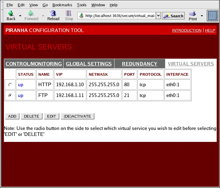
The VIRTUAL SERVERS panel displays
information for each currently defined virtual server. Each table
entry shows the status of the virtual server, the server name, the
virtual IP assigned to the server, the netmask of the virtual IP,
the port number to which the service communicates, the protocol
used, and the virtual device interface.
Each server displayed in the VIRTUAL
SERVERS panel can be configured on subsequent screens or
subsections.
To add a service, click the ADD button.
To remove a service, select it by clicking the radio button next to
the virtual server and click the DELETE
button.
To enable or disable a virtual server in the table click its
radio button and click the (DE)ACTIVATE
button.
After adding a virtual server, you can configure it by clicking
the radio button to its left and clicking the EDIT button to display the VIRTUAL SERVER subsection.
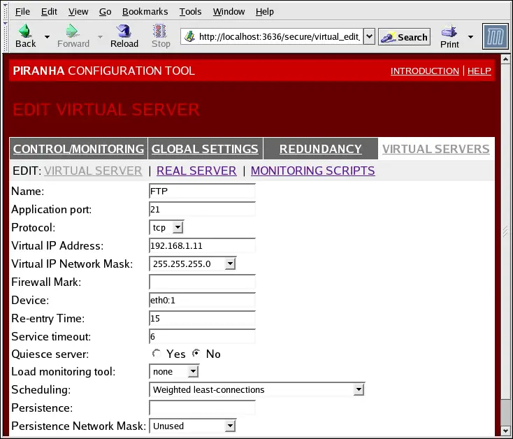
The VIRTUAL SERVER subsection panel
shown in Figure 10-6
allows you to configure an individual virtual server. Links to
subsections related specifically to this virtual server are located
along the top of the page. But before configuring any of the
subsections related to this virtual server, complete this page and
click on the ACCEPT button.
- Name
-
Enter a descriptive name to identify the virtual server. This
name is not the hostname for the machine,
so make it descriptive and easily identifiable. You can even
reference the protocol used by the virtual server, such as
HTTP.
- Application port
-
Enter the port number through which the service application will
listen. Since this example is for HTTP services, port 80 is
used.
-
Choose between UDP and TCP in the drop-down menu. Web servers
typically communicate via the TCP protocol, so this is selected in
the example above.
- Virtual IP Address
-
Enter the virtual server's floating IP address in this text
field.
-
Set the netmask for this virtual server with the drop-down
menu.
- Firewall Mark
-
Do not enter a firewall mark integer
value in this field unless you are bundling multi-port protocols or
creating a multi-port virtual server for separate, but related
protocols. In this example, the above virtual server has a
Firewall Mark of 80 because we are bundling
connections to HTTP on port 80 and to HTTPS on port 443 using the
firewall mark value of 80. When combined with persistence, this
technique will ensure users accessing both insecure and secure
webpages are routed to the same real server, preserving state.
 |
Warning |
| |
Entering a firewall mark in this field allows IPVS to recognize
that packets bearing this firewall mark are treated the same, but
you must perform further configuration outside of the Piranha Configuration Tool to actually assign the
firewall marks. See Section 9.3
Multi-port Services and LVS Clustering for instructions
on creating multi-port services and Section 9.4 FTP In an LVS Cluster for
creating a highly available FTP virtual server.
|
- Device
-
Enter the name of the network device to which you want the
floating IP address defined the Virtual IP
Address field to bind.
You should alias the public floating IP address to the Ethernet
interface connected to the public network. In this example, the
public network is on the eth0 interface,
so eth0:1 should be entered as the
device name.
- Re-entry Time
-
Enter an integer value which defines the length of time, in
seconds, before the active LVS router attempts to bring a real
server back into the cluster after a failure.
- Service Timeout
-
Enter an integer value which defines the length of time, in
seconds, before a real server is considered dead and removed from
the cluster.
- Quiesce server
-
When the Quiesce server radio button is
selected, anytime a new real server node comes online, the
least-connections table is reset to zero so the active LVS router
routes requests as if all the real servers were freshly added to
the cluster. This option prevents the a new server from becoming
bogged down with a high number of connections upon entering the
cluster.
- Load monitoring tool
-
The LVS router can monitor the load on the various real servers
by using either rup or ruptime. If you select rup
from the drop-down menu, each real server must run the rstatd service. If you select ruptime, each real server must run the rwhod service.
 |
Caution |
| |
Load monitoring is not the same as load
balancing and can result in hard to predict scheduling behavior
when combined with weighted scheduling algorithms. Also, if you use
load monitoring, the real servers in the cluster must be Linux
machines.
|
- Scheduling
-
Select your preferred scheduling algorithm from the drop-down
menu. The default is Weighted
least-connection. For more information on scheduling
algorithms, see Section 7.3.1 Scheduling
Algorithms.
- Persistence
-
If an administrator needs persistent connections to the virtual
server during client transactions, enter the number of seconds of
inactivity allowed to lapse before a connection times out in this
text field.
 |
Important |
| |
If you entered a value in the Firewall
Mark field above, you should enter a value for persistence as
well. Also, be sure that if you use firewall marks and persistence
together, that the amount of persistence is the same for each
virtual server with the firewall mark. For more on persistence and
firewall marks, refer to Section
7.5 Persistence and Firewall Marks.
|
-
To limit persistence to particular subnet, select the
appropriate network mask from the drop-down menu.
 |
Note |
| |
Before the advent of firewall marks, persistence limited by
subnet was a crude way of bundling connections. Now, it is best to
use persistence in relation to firewall marks to achieve the same
result.
|
|
Warning |
| |
Remember to click the ACCEPT button
after making any changes in this panel. To make sure you do not
lose changes when selecting a new panel.
|
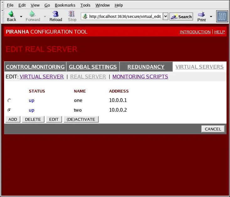
Clicking on the REAL SERVER subsection
link at the top of the panel displays the EDIT
REAL SERVER subsection. It displays the status of the physical
server hosts for a particular virtual service.
Click the ADD button to add a new
server. To delete an existing server, select the radio button
beside it and click the DELETE button.
Click the EDIT button to load the
EDIT REAL SERVER panel, as seen in Figure
10-8.
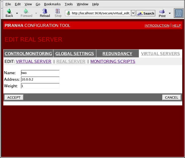
This panel consists of three entry fields:
- Name
-
A descriptive name for the real server.
 |
Tip |
| |
This name is not the hostname for the
machine, so make it descriptive and easily identifiable.
|
- Address
-
The real server's IP address. Since the listening port is
already specified for the associated virtual server, do not add a
port number.
- Weight
-
An integer value indicating this host's capacity relative to
that of other hosts in the pool. The value can be arbitrary, but
treat it as a ratio in relation to other real servers in the
cluster. For more on server weight, see Section 7.3.2
Server Weight and Scheduling.
|
Warning |
| |
Remember to click the ACCEPT button
after making any changes in this panel. To make sure you do not
lose any changes when selecting a new panel.
|
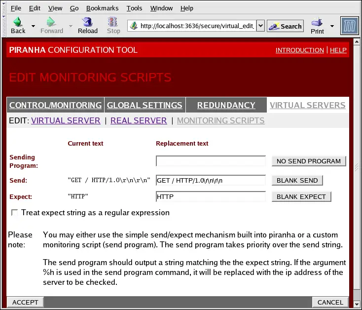
Click on the MONITORING SCRIPTS link at
the top of the page. The EDIT MONITORING
SCRIPTS subsection allows the administrator to specify a
send/expect string sequence to verify that the service for the
virtual server is functional on each real server. It is also the
place where the administrator can specify customized scripts to
check services requiring dynamically changing data.
- Sending Program
-
For more advanced service verification, you can use this field
to specify the path to a service-checking script. This
functionality is especially helpful for services that require
dynamically changing data, such as HTTPS or SSL.
To use this functionality, you must write a script that returns
a textual response, set it to be executable, and type the path to
it in the Sending Program field.
|
Tip |
| |
To ensure that each server in the real server pool is checked,
use the special token %h after the
path to the script in the Sending Program
field. This token is replaced with each real server's IP address as
the script is called by the nanny
daemon.
|
The following is a sample script to use as a guide when
composing an external service-checking script:
#!/bin/sh

TEST=`dig -t soa example.com @$1 | grep -c dns.example.com

if [ $TEST != "1" ]; then
        echo "OK
else
        echo "FAIL"
fi
|
|
Note |
| |
If an external program is entered in the Sending Program field, then the Send field is ignored.
|
- Send
-
Enter a string for the nanny daemon to
send to each real server in this field. By default the send field
is completed for HTTP. You can alter this value depending on your
needs. If you leave this field blank, the nanny daemon attempts to open the port and assume
the service is running if it succeeds.
Only one send sequence is allowed in this field, and it can only
contain printable, ASCII characters as well as the following escape
characters:
- Expect
-
Enter a the textual response the server should return if it is
functioning properly. If you wrote your own sending program, enter
the response you told it to send if it was successful.
|
Tip |
| |
To determine what to send for a given service, you can open a
telnet connection to the port on a real
server and see what is returned. For instance, FTP reports 220 upon
connecting, so could enter quit in the
Send field and 220 in the Expect
field.
|
|
Warning |
| |
Remember to click the ACCEPT button
after making any changes in this panel. To make sure you do not
lose any changes when selecting a new panel.
|
Once you have configured virtual servers using the Piranha Configuration Tool, you must copy
specific configuration files to the backup LVS router. See Section 10.7 Synchronizing Configuration
Files for details.
|
|
|