Specify the following information depending on whether the
device is connected to one of several supported fence devices.
| Field |
Description |
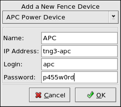
| Name |
A name for the APC device connected to the cluster. |
| IP Address |
The IP address assigned to the device. |
| Login |
The login name used to access the device. |
| Password |
The password used to authenticate the connection to the
device. |
Table 3-4. Configuring an APC Fence Device
| Field |
Description |
| Name |
A name for the IBM Bladecenter device connected to the
cluster. |
| IP Address |
The IP address assigned to the device. |
| Login |
The login name used to access the device. |
| Password |
The password used to authenticate the connection to the
device. |
Table 3-5. Configuring an IBM Blade Center that Supports
Telnet
| Field |
Description |
| Name |
A name for the Brocade device connected to the cluster. |
| IP Address |
The IP address assigned to the device. |
| Login |
The login name used to access the device. |
| Password |
The password used to authenticate the connection to the
device. |
Table 3-6. Configuring a Brocade Fibre Channel Switch
| Field |
Description |
| IP Address |
The IP address assigned to the PAP consle. |
| Login |
The login name used to access the PAP console. |
| Password |
The password used to authenticate the connection to the PAP
console. |
Table 3-7. Configuring a Bull Platform Administration
Processor (PAP) Interface
| Field |
Description |
| IP Address |
The IP address assigned to the IPMI port. |
| Login |
The login name of a user capable of issuing power on/off
commands to the given IPMI port. |
| Password |
The password used to authenticate the connection to the IPMI
port. |
Table 3-8. Configuring a Bull Intelligent Platform Management
Interface (IPMI)
| Field |
Description |
| Name |
A name for the BladeFrame device connected to the cluster. |
| CServer |
The hostname (and optionally the username in the form of
username@hostname) assigned to the
device. Refer to the fence_egenera(8)
manpage for more information. |
Table 3-9. Configuring an Egenera BladeFrame
| Field |
Description |
| Name |
A name for the GNBD device used to fence the cluster. Note that
the GFS server must be accessed via GNBD for cluster node fencing
support. |
| CServer |
The hostname (and optionally the username in the form of
username@hostname) assigned to the
device. Refer to the fence_egenera(8)
manpage for more information. |
Table 3-10. Configuring a Global Network Block Device (GNBD)
fencing agent
| Field |
Description |
| Name |
A name for the server with HP iLO support. |
| Login |
The login name used to access the device. |
| Password |
The password used to authenticate the connection to the
device. |
| Hostname |
The hostname assigned to the device. |
Table 3-11. Configuring an HP Integrated Lights Out (iLO)
card
| Field |
Description |
| Name |
A name to assign the Manual fencing agent. Refer to fence_manual(8) for more information. |
Table 3-12. Configuring Manual fencing
| Field |
Description |
| Name |
A name for the McData device connected to the cluster. |
| IP Address |
The IP address assigned to the device. |
| Login |
The login name used to access the device. |
| Password |
The password used to authenticate the connection to the
device. |
Table 3-13. Configuring a McData Fibre Channel Switch
| Field |
Description |
| Name |
A name for the SanBox2 device connected to the cluster. |
| IP Address |
The IP address assigned to the device. |
| Login |
The login name used to access the device. |
| Password |
The password used to authenticate the connection to the
device. |
Table 3-14. Configuring a QLogic SanBox2 Switch
| Field |
Description |
| Name |
A name for the Vixel switch connected to the cluster. |
| IP Address |
The IP address assigned to the device. |
| Password |
The password used to authenticate the connection to the
device. |
Table 3-15. Configuring a Vixel SAN Fibre Channel
Switch
| Field |
Description |
| Name |
A name for the WTI power switch connected to the cluster. |
| IP Address |
The IP address assigned to the device. |
| Password |
The password used to authenticate the connection to the
device. |
Table 3-16. Configuring a WTI Network Power Switch